|
TDXM-DC温度扫描仪 / 高温计
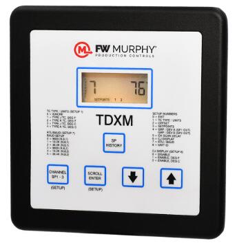
TDXM-DC设计了一个7字符、7部分的液晶显示窗口,1/2英寸。(13mm),易读字。还位于面板上的膜键容易配置。高度可靠和多用途,TDXM-DC接受多达24类型j或k接地或不接地热电偶。每个通道有三个可调设置点SP1,SP2和SP3。次级方案1、次级方案2和次级方案3的集合点与次级方案1、次级方案2和次级方案3的产出相对应。此外,它还具有可选择的特性,可以监控和报警,或在与平均值偏差的情况下关闭最多两组温度(GRP/DEV;偏离平均值)。一组可能是排气温度,另一组可能是承受温度。
TDXM-DC提供一个独特的可配置温度扫描仪/高温计,内置电源。
- 带有内置电源的可配置温度扫描仪/高温计
- 多达24个频道的扫描
- 每个频道三个(3)可调整的行程点
- 接受J或K型接地或不接地热电偶组合
- 两个单独的组,具有可选择的偏差行程函数
- 由10至32个VDC系统供电
- 串行通信端口
- 使用MCONIN配置和监控软件
- 核证用于第一类第2项C和D类危险地点

TDXM-DC emperature Scanner / Pyrometer
TDXM-DC温度扫描仪 / 高温计

TDXM-DC能够通过内置的RS485串行通信端口与控制器、PLCS、计算机或SCAD(监控控制和数据采集)系统进行通信。
TDXM-DC可用于10-32个VDC系统。
用户界面(面板)
用户界面包括一个数字液晶和一个五按钮膜键盘,用于读取和通道配置。热电偶类型可以选择和设置通过一系列设置菜单点输入。
热电偶类型
TDXM-DC上的24个通道的每一个都可以配置为j或k型热电偶,温度单位可以选择为每一通道的°F或°C读数。可以将未使用的通道设置为忽略,并且不会在显示器中看到,也不会导致故障旅行。
控制选项
每个TDXM-DC具有三个输出功能:两个场效应晶体管输出和一个格式C继电器输出。每个通道有三个设置点,每个输出一个.这样可以通过通过一个输出对通道集进行分组来提高系统的灵活性。
起点历史
在非易失性内存中存储每个输出的最后一次设置点旅行。例如,如果频道1的SP1是最后一个SP1触发,那么当为SP1访问设置点历史时,LCD显示器将显示:SP1。
传感器输入和终端
tdxm-dc接受最多24个j或k型接地或无接地 * 热电偶使用24对螺旋型连接。每对都有一个工厂的跳楼人。在超过设定点后2秒钟内检测到任何绊点。
RS485串口
模块背面的RS485串口(MODBUSRTU客户端)用于与微控制器、PC、PLCS和SCAD系统的通信。建议当Tdxm-dc是最后一个连接在天链配置中的设备时,使用终止电阻(客户提供的)。可以使用键盘设置波特率、停止位数和服务器节点数。交流是半双工的。支持MODBUS的功能代码3和6。
* 我们建议使用不接地热电偶。接地热电偶读数的错误可能是不同设备之间接地差异的结果。
Temperature Scanner/Pyrometer
The TDXM-DC provides a unique configurable temperature scanner/pyrometer with a built-in power supply.
- Configurable temperature scanner/pyrometer with a built-in power supply
- Scans up to 24 channels
- Three (3) adjustable trip points per channel
- Accepts any combination of J or K type grounded or ungrounded thermocouples
- Two separate groups with deviation trip functions selectable
- Powered by 10 to 32 VDC systems
- RS485 serial communications port
- Uses MConfig? configuration and monitoring software
- CSA certified for use in Class I, Division 2, Groups C & D hazardous locations
The TDXM-DC's design features a 7-character, 7-segment Liquid Crystal Display window with 1/2 in. (13 mm), easy-to-read characters. Also located on the faceplate are membrane keys for easy configuring. Highly reliable and versatile, the TDXM-DC accepts up to 24 type J or K grounded or ungrounded thermocouples. Each channel has three adjustable set points SP1, SP2 and SP3. The SP1, SP2 and SP3 set points correspond to the SP1, SP2 and SP3 outputs. Additionally, it has the selectable feature to monitor and alarm or shut down on deviation from an average for up to two groups of temperatures (GRP/DEV; deviation from average). One group could be exhaust temperatures, and another group could be bearing temperatures.
The TDXM-DC is capable of communicating with controllers, PLCs, computers or SCADA (Supervisory Control & Data Acquisition) systems by a built-in RS485 serial communications port.
The TDXM-DC is available for 10 – 32 VDC systems.
User Interface (Faceplate)
The User Interface includes a numeric LCD and a five-button membrane keypad for readout and channel configuration. Thermocouple types can be selected and set points entered through a series of setup menus.
Thermocouple Types
Each of the 24 channels on the TDXM-DC can be configured as either J or K type thermocouples and temperature units can be selected as °F or °C readout for each channel. Unused channels can be set to Ignore and will not be seen in the display and will not cause fault trips.
Control Options
Each TDXM-DC features three outputs: two Field Effect Transistor (FET) outputs and one Form-C Relay output. Each channel has three set points; one for each output. This allows for greater system flexibility by grouping sets of channels through one output.
Set Point History
The TDXM-DC stores the last set point trip for each output in non-volatile memory. For instance, if SP1 of channel 1 was the last SP1 tripped, the LCD display will read: SP1 1 when the set point history is accessed for SP1.
Sensor Inputs and Terminals
The TDXM-DC accepts up to 24 either J or K type grounded or ungrounded * thermocouples using 24 pairs of screw-type connections. Each pair has a jumper from the factory. Any tripped set point is detected within two seconds after the set point is exceeded.
RS485 Serial Port
The RS485 serial port (Modbus RTU client) on the back of the module is provided for communicating with microcontrollers, PCs, PLCs and SCADA systems. It is recommended that a termination resistor (customer supplied) be used when the TDXM-DC is the last device connected in a daisy-chain configuration. The baud rate, number of stop bits and server node number can be set using the keypad. Communication is half-duplex. Modbus RTU function codes 3 and 6 are supported.
* We recommend the use of ungrounded thermocouples. Errors in readings with grounded thermocouples can be the result of differences in grounding between different devices.
|
